Mesh attachments
Mesh attachments are not available in Spine Essential.
A mesh attachment is a polygon that is textured with an image. A polygon is defined inside the image, then its vertices can be manipulated to bend and deform the image. Meshes also have the advantage that the polygon can exclude parts of an image from rendering, which can improve performance.
Meshes can be deformed automatically when bones are transformed by using weights.
Mesh vertex positions can be keyed in animations.
See the mesh attachment example projects and tips for usage examples.
Setup
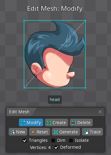
To create a mesh, first create a region attachment, then check Mesh in the region attachment's tree properties.
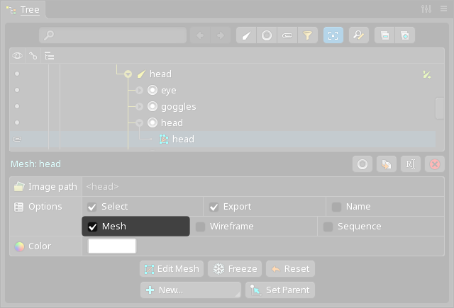
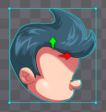
The region attachment is converted to a mesh attachment with 4 vertices, one in each corner. The mesh vertices can be modified using edit mode.
Properties
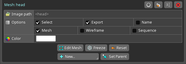
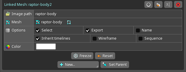
See the common attachment properties for the Select, Export, Name, Color, and Set Parent properties.
Image path
When the image path is blank, the mesh attachment's name is used to find the image. When the image path is set, it is used instead of the mesh attachment's name. See image file lookup for more information.
Mesh
When unchecked, the mesh attachment is changed back into a region attachment.
Wireframe
When checked, the meshes vertices and edges are drawn even when the mesh is not selected. This can be helpful for considering the mesh vertices when placing bone origins.
Sequence
See sequence for more information.
Edit Mesh
Clicking the Edit Mesh button enters edit mode, which is for modifying the mesh's vertices.
Freeze
The Freeze button sets rotation to 0 and scale to 1 for the current vertex positions.
This is possible because a mesh does not really have a rotation or scale. It has only a number of vertices, each of which has a position. Spine provides rotation and scale values for convenience, to allow manipulation similar to other attachments. The rotation and scale are adjusted when the Rotate or Scale tools are used on the entire attachment.
A mesh doesn't have translation, either. The translation values shown are the centroid of the hull vertices.
Reset
This should not be confused with the Reset button in edit mode.
The Reset button moves the mesh's vertex positions to match the UVs, so the mesh is not deformed. The vertices will match the UVs as defined in edit mode with Deformed unchecked. Since the vertices are given new positions, the mesh may shift position if it was deformed. All weights are removed from the mesh and any deform keys in animations are deleted.
When vertices are added, removed, or translated in edit mode, the vertices outside of edit mode may not be in the desired positions. Reset can be used to remove any deformation from the mesh.
Edit mode
Edit mode allows for creating, modifying, and deleting the mesh's vertices.
The outline view can be used to see the entire skeleton while editing a mesh.
The Edit Mesh button enters edit mode. It can be exited at any time by clicking the Edit Mesh button again, by closing the edit mode dialog, or by pressing spacebar or escape.
Right click switches between the Modify, Create, and Delete tools.
Modify tool
The Modify tool allows existing vertices to be moved. Double click to delete a vertex.
Create tool
The Create tool allows new vertices to be created by clicking and new edges to be created by dragging. Hold shift to disable snapping to a vertex. When dragging to create an edge, hold shift to snap vertically or horizontally. Double click to delete a vertex.
Delete tool
The Delete tool allows vertices or edges to be deleted by clicking. Multiple vertices can be selected by holding ctrl (cmd on Mac) or dragging to box select.
New vertices mode
The New button deletes all vertices and enters the new vertices mode. This mode allows the hull of the mesh to be defined by clicking to create new vertices. Vertices can also be translated by dragging or deleted by double clicking. To complete the mesh hull, exit the new vertices mode by clicking the first vertex to close the hull or by clicking the New button again.
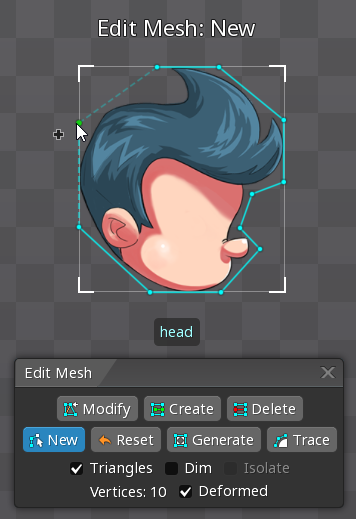
The new vertices mode allows the mesh hull to be defined quickly. Alternatively, the Create tool can be used to create vertices and edges, then the Delete tool used to remove any unwanted vertices or edges.
Reset vertices
This should not be confused with the Reset button in the tree properties.
The Reset button removes all vertices and replaces them with 4 vertices, one in each corner. All weights are removed and any deform keys in animations are deleted. The Reset button is useful to start over.
Generate
The Generate button adds new vertices to the mesh at positions that will benefit deformation the most. All weights are removed and any deform keys in animations are deleted.
Generate can be clicked multiple times to add more and more vertices. Existing vertices are not moved, so Generate can be used to automatically fill in a mesh after manually adding vertices around important features in the image.
If a mesh has vertices in all 4 corners, such as after clicking Reset, then Generate will create a grid with vertices arranged in rows and columns. Clicking Generate multiple times will create an increasingly dense grid of vertices.
Trace
The Trace button creates a mesh hull automatically. All weights are removed and any deform keys in animations are deleted.
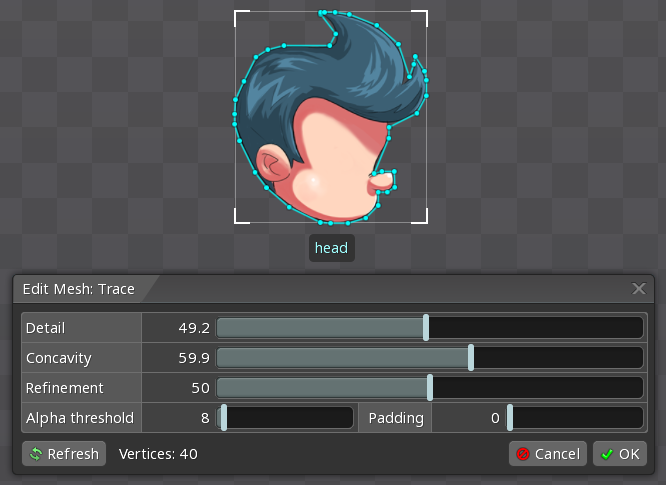
A number of settings can be configured to affect how the mesh hull is created:
Detailcontrols how many vertices are used.Concavitycontrols the priority for placing vertices into concave areas.Refinementcontrols the time and effort spent finding an optimal solution.Alpha thresholdcauses pixels which have an alpha value below the threshold to be ignored.Paddingadds space between the image and the hull.
Refresh repeats creating the hull using the same settings. The hull is created slightly differently each time, so it can be useful to create it a few times and choose the hull that best matches your needs.
Triangles
When checked, dashed lines are drawn between vertices to show how the mesh is triangulated. The triangulation determines how the mesh deforms. Seeing the triangles helps with deciding where edges are needed.
Dim
When checked, the mesh image is dimmed so the vertices, edges, and triangles can be seen more easily.
Isolate
When checked, other attachments are not drawn so the mesh can be seen more easily.
Deformed
When checked, the mesh is shown as it looks outside of edit mode. When a vertex is translated, it changes both the vertex position outside of edit mode and the texture coordinates. The vertex positions are limited to the image bounds and gray lines appear when near the boundary.
The outline view can be used to visualize the mesh while changing the texture coordinates.
When unchecked, the entire mesh image is shown without any deformation. Vertices are shown at the position on the image that will used for the vertex when the mesh is drawn. This is known as the "texture coordinates" or UVs. When a vertex is translated, it changes the texture coordinates but does not change the position of the vertex outside of edit mode.
If this is undesirable, Reset can be used outside edit mode so the vertex positions match the texture coordinates.
Edges
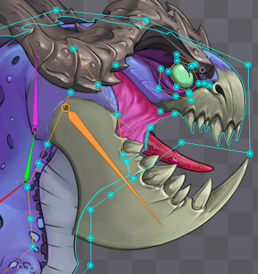
In addition to vertices, a mesh also has "edges" which are connections between vertices. Spine automatically handles the edges around the mesh hull, shown in cyan. Inside the hull, Spine automatically connects all the vertices with edges, shown as dashed gray lines in edit mode when Triangles is checked.
The edges between the vertices determine how the mesh will deform when vertices are translated. The Create tool in edit mode can be used to create edges manually, shown in orange.

It is unnecessary to create manual edges (orange) over the edges Spine creates automatically (gray). Doing so does not change the mesh triangulation, but may make selection easier by clicking the edge or using edge loop selection.
Vertices and edges can be added inside the mesh around features on the image to control how they are deformed. The automatically computed edges (gray) will never cross a manual edge (orange), so specifying edges manually provides complete control over how vertices are connected.
Edge examples
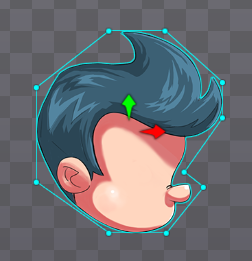
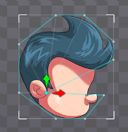
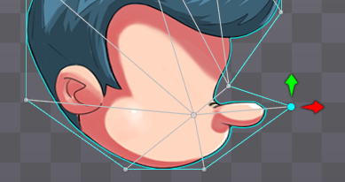
This example shows how to control mesh deformation by adding vertices and edges. We have made the hull for spineboy's head and now want to make the nose stretch.

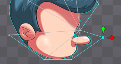
When a vertex is translated, only the triangles that include the vertex are deformed. This stretches the tip but not the base of the nose and also stretches some of the cheek. By adding a new vertex, we get different triangles and the mesh will deform differently.

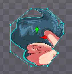
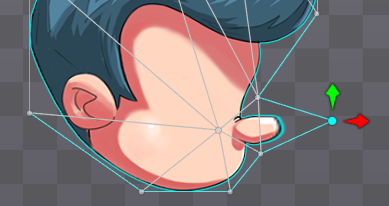
Above, a new vertex was added at the base of the nose, resulting in different triangles. Now the vertex we are translating belongs to two triangles. When the vertex is translated, it deforms both triangles. This stretches the entire nose, but also a lot of the cheek. Another vertex is needed to stop the cheek from deforming.

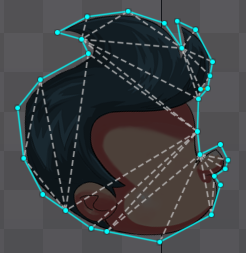
Above, a new vertex was added under the nose. The entire nose is now contained within two triangles, but translating the vertex deforms only one of them. To fix this, in edit mode we need to create an edge by selecting the Create tool and dragging between the vertices.

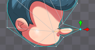
The new edge (orange) causes the nose triangles to connect differently and the nose can now be deformed without affecting the rest of the head.
Edge loop selection
If a mesh edge is selected while shift is held, edge loop selection is performed. This selects the edge and all neighboring edges in a line. While holding shift, ctrl (cmd on Mac) can also be held to add to the current selection.
Vertex placement
There are many factors to consider when choosing where to place mesh vertices. Besides the information below, our series of blog posts on meshes provides a lot of great tips for designing your meshes:
Hull size
Trace can place vertices as close as possible to borders inside the image, without cutting off any pixels.
The mesh hull should exclude as much blank space as possible. For example, a tree image may have a lot of blank space on either side of the trunk. Even if the tree doesn't need to be deformed, using a mesh to exclude pixels can be beneficial.
Pixels outside the hull are not drawn at all and do not count against the fill rate. This can improve performance for a game that is fill rate limited, especially for large images with a lot of blank space.
When texture packing using polygons, mesh texture atlas regions can be packed very tightly, fitting more images in a single texture atlas page. Even when not packing using polygons, whitespace stripping can remove all pixels outside the mesh hull.
Hull edges
MSAA is not needed if you never use a mesh hull to cut off nontransparent pixels.
If the mesh hull is used to cut off nontransparent pixels, the resulting edge will have aliasing. This means pixels along the edge are either shown or not shown – the edge will jagged, not smooth. To get smooth edges in this case, multisample anti-aliasing (MSAA) can be used when the mesh is rendered. This can be enabled for the Spine editor in the settings dialog and for image or video exports on the export dialog. To get smooth edges at runtime, MSAA needs to be configure for your game toolkit.
Nontransparent pixels at the edge of an image's bounds may also cause aliasing, even though the pixels are not being cut off. This occurs in the Spine editor because it loads individual images and pixels against the image edge don't have transparent pixels next to them for filtering to smooth. At runtime, when loading from a texture atlas there is usually at least 1 pixel of transparent space around the image, so this aliasing will not occur.
Holes
Meshes can be concave but cannot have holes. If a hole is needed, usually it is sufficient to use transparent pixels in the mesh's image. For example, the image for a head mesh can use transparent pixels for the eye holes.
Using two meshes is done most easily by first making one mesh that encompasses the whole image and has vertices around the inside of the hole. Next, duplicate the mesh and modify both meshes by deleting vertices until each makes up one half around the hole.
If the hole needed is large, it may be undesirable to draw a large number of transparent pixels, which can negatively affect the fill rate. Also, a large image with a lot of blank space can take up a lot of room in the texture atlas. In that case two meshes can be used, one for each half of the image around the hole.
Vertex count
Generally the number of vertices in a mesh should be kept to a minimum to reduce CPU usage. The position of each vertex must be computed by the CPU each frame. This is a fast operation, but many skeletons on screen at once with many meshes, each having many vertices, can add up to thousands of positions that need to be computed.
When using weights, each bone affecting a vertex adds an additional vertex transform. For example, a mesh with 100 vertices requires 100 vertex transforms. If the same mesh has 2 bones affecting every vertex, it requires 200 vertex transforms. If a mesh is bound to many bones and smoothing is used to spread the weights out, it can greatly increase the number of vertex transforms required. Use prune to remove unnecessary weights and limit the number of bones that can affect a vertex.
Deformation
Where vertices are placed and how they are connected by edges determines how the mesh deforms. Most or all deformation should be done using weights. Using deform keys should be avoided or kept to a minimum.
Transform tools
Mesh vertices can be moved outside of edit mode by using the transform tools. The entire mesh can be rotated, translated, and scaled like any other attachment.
Individual vertices can be translated with any transform tool by dragging, which will deform the image. Multiple vertices can be selected by holding ctrl (cmd on Mac), then clicking or dragging to box select. The selected vertices can be deselected by pressing spacebar or escape, or by clicking in any empty space.
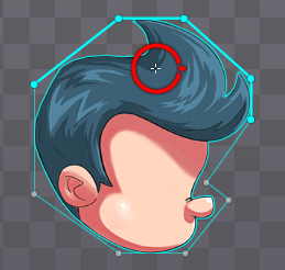
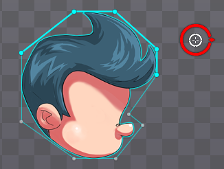
The origin used for rotation or scaling can be changed. Mouse over the small crosshair at the center of the Rotate or Scale tool until a circle appears, then drag the origin to the desired position. The origin will automatically snap to vertices.
Moving vertices in setup mode changes the deformation for the setup pose. Moving vertices in animate mode is done to set deform keys. Deform keys should generally be avoided and weights used instead.
Rotation and scale are only used to move the vertices. The amount of rotation and scale used is not stored in deform keys. Only the vertex positions are stored and interpolation between deform keys always moves the vertices in a straight line.
Image resize
If an image file a mesh uses is made larger outside of Spine, Spine will ask if you would like to scale the texture coordinates to keep the image contents the same size.
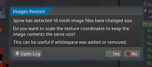
This is useful when whitespace has been added to any of the edges of the image. When that is the case, answer Yes to adjust the texture coordinates so the image contents are kept the same size, centered by how much larger the image is. Afterward, if the whitespace was not added evenly to all sides of the image, the texture coordinates may need to be manually adjusted in edit mode. Select all vertices by holding ctrl (cmd on Mac), then drag to box select. Next, use the Modify tool to move the vertices to the correct position.
If the image was made larger because its contents need to be bigger, keeping the texture coodinates at the old size may not be desirable. In that case, answering No will not modify the mesh. Since the texture coordinates are stored normalized, they will scale up or down when the image size changes.
Linked meshes
It is common to need to reuse a mesh with a different image. For example, you have animated a mesh for a flag and now you want to use various different flag images with the same mesh and animations.
Duplicating the mesh and its deform keys isn't ideal because it results in two separate meshes and sets of keys, so any changes to the mesh or keys need to be made multiple times.
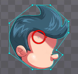
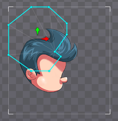
Linked meshes provide a better solution to this problem. To create a linked mesh, in the mesh's tree properties click New... Linked Mesh. The linked mesh shares its mesh structure with the source mesh: vertices, edges, texture coordinates, and weights. Any changes made to these for the source mesh will also affect all its linked meshes.
To indicate that changing a vertex will affect other meshes, the vertices appear with a ring around them:
To use a different image for the linked mesh, rename it or set an image path, as normal.
If Inherit timelines is checked, then any deform keys for the source mesh will also affect the linked mesh. If Inherit timelines is not checked, deform keys for the linked mesh can be set as normal, separately from the source mesh.
Linked meshes must always be under the same slot as the source mesh. Moving the source mesh or any linked mesh to another slot will cause all the others to also be moved.
Linked meshes may be under skin placeholders in different skins, as long as they are under the same slot as the source mesh.
Video